
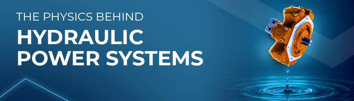
A pump roughly the size of a shoebox, connected to a hydraulic cylinder not much wider than a human arm, can generate enough force to bend a steel beam. At first glance, this may seem counterintuitive, especially when the components responsible for producing such enormous forces appear relatively compact. However, once the physics behind hydraulic systems becomes clear, the principle is easier to understand: the real advantage lies not simply in the size of the components, but in how pressure is generated, transmitted, and converted into mechanical force.
Hydraulic technology is widely used across industrial machinery, construction equipment, manufacturing systems, and mobile applications because it allows engineers to produce substantial forces within relatively compact assemblies. The same fundamental principle supports everything from hydraulic presses and lifting platforms to excavators, injection moulding machines, and specialized production equipment.
The foundation of hydraulic power is Pascal’s Law, which states that pressure applied to a confined fluid is transmitted throughout the fluid and acts in all directions. In a hydraulic system, a pump supplies fluid flow, while the resistance of the connected components allows pressure to develop. This pressure acts on the effective area of a cylinder piston, generating a mechanical force that can move heavy loads or perform demanding industrial operations.
The relationship between pressure, area, and force is expressed through a straightforward equation:
Force = Pressure × Area
This relationship explains why a relatively small input force can produce a much larger output force when hydraulic components have different effective areas. If pressure acts on a larger piston area, the resulting force increases proportionally, provided the system can supply the required pressure and flow.
The trade-off is displacement and speed. A larger cylinder requires more fluid to move through the same stroke, meaning that force multiplication does not create energy from nothing. Instead, hydraulic systems exchange movement distance and speed for force, much like a mechanical lever, while offering the additional advantage of transmitting power through flexible pipework and compact fluid circuits.
One of the main advantages of hydraulic systems is their ability to deliver high forces while maintaining a relatively compact design. Mechanical linkages can require substantial space and carefully arranged components, whereas hydraulic power can be transmitted through pipes and hoses that follow the layout of the machine. This gives engineers greater flexibility when designing equipment with limited installation space, complex movement paths, or multiple working positions.
Hydraulics also allows force and motion to be controlled through valves, pressure regulators, and flow-control components. By selecting appropriate components and configuring the circuit correctly, engineers can control cylinder movement, regulate operating pressure, and coordinate several actuators within one machine.
These characteristics make hydraulic systems particularly useful when equipment must handle heavy loads, apply substantial clamping forces, or maintain controlled movement under changing operating conditions. However, achieving the intended performance requires more than selecting a pump and cylinder with sufficient nominal capacity. The entire circuit must be designed around the machine’s actual operating requirements, including expected loads, movement speeds, duty cycles, and environmental conditions.
Let’s discuss how our engineering team can support your machine design, technical calculations, and production requirements.
Although hydraulic systems are based on a well-established physical principle, their behaviour can change significantly under real operating conditions. One important factor is fluid viscosity, which describes a fluid’s resistance to flow. Hydraulic oil generally becomes less viscous as its temperature increases and more viscous as it cools, influencing how fluid moves through the circuit and how individual components respond.
When the oil is too cold, increased viscosity can lead to greater flow resistance, slower actuator movement, and higher pressure losses in certain parts of the system. When the oil becomes excessively hot, reduced viscosity may increase internal leakage and weaken the fluid film that protects moving surfaces from wear. Temperature also affects seals, lubrication conditions, and the overall performance of hydraulic components.
For this reason, hydraulic systems must be evaluated across their expected operating temperature range rather than under a single ideal condition. Correct fluid selection, suitable filtration, effective cooling, and an appropriate warm-up procedure can all contribute to stable operation.
Understanding these factors is particularly important in industrial environments where equipment operates for extended periods, experiences frequent load changes, or must perform consistently despite fluctuations in ambient temperature.
Another important challenge is hydraulic shock, which occurs when fluid velocity changes rapidly, for example when a valve closes suddenly or a moving actuator is stopped abruptly. Because fluid in motion has momentum and the circuit has finite elasticity, a rapid change in flow can generate a pressure transient that travels through the system.
Depending on the operating conditions, these pressure spikes can exceed normal working pressure and place additional stress on pipes, hoses, seals, valves, and other components. Repeated pressure surges may contribute to premature wear, leakage, component damage, and unexpected maintenance requirements.
Engineers can reduce these risks through careful circuit design and appropriate selection of protective components. Pressure relief valves help limit excessive pressure, while hydraulic accumulators can absorb certain transient effects and provide additional fluid when required. Valve response characteristics, pipe dimensions, actuator speed, and the arrangement of the hydraulic circuit must also be considered when evaluating potential pressure surges.
The important point is that nominal pressure ratings alone do not always describe what happens during rapid operating changes. Understanding the system’s dynamic behaviour helps engineers identify potential problems before they affect equipment performance or production schedules.
Hydraulic systems also depend heavily on fluid cleanliness. Particles that are almost impossible to see with the naked eye can cause measurable damage when they circulate through components with very small clearances. Pumps, proportional valves, servo valves, and other precision elements can be particularly sensitive to contamination, depending on their design and operating conditions.
Contaminants may enter a system during assembly, maintenance, fluid filling, or through damaged seals and inadequate filtration. Once inside the circuit, particles can contribute to abrasive wear, interfere with valve movement, obstruct small passages, and accelerate the deterioration of internal surfaces.
The consequences are not always immediate. A component may continue operating while its internal clearances gradually change, leakage increases, or response becomes less consistent. By the time the problem becomes visible, identifying the original cause can require detailed inspection and analysis.
Appropriate filtration, clean maintenance procedures, correct fluid handling, and regular monitoring are therefore essential parts of hydraulic system management. For demanding applications, engineers may also define fluid cleanliness targets and monitoring procedures based on component requirements and applicable technical guidance.
The performance of a hydraulic machine depends on how its components interact. A pump may provide sufficient flow, and a cylinder may be capable of generating the required force, but the complete system can still perform poorly if the valves, pipework, fluid characteristics, and control strategy are not properly matched to the application.
For example, selecting a pump without considering the required actuator speed may lead to inefficient operation or inadequate performance during demanding production cycles. Incorrect valve sizing can create unnecessary pressure losses, while unsuitable pipe dimensions may increase flow resistance and heat generation. If these factors are overlooked during development, the resulting problems may only become apparent during commissioning or after the machine enters regular operation.
A comprehensive engineering approach evaluates the complete operating sequence, expected loads, pressure requirements, movement speeds, thermal behaviour, and maintenance conditions. It also considers how the hydraulic circuit interacts with mechanical structures, electrical controls, and the wider production process.
At GFE Solutions, we believe that engineering decisions should be assessed in the context of the complete machine. Through design engineering, technical calculations, and coordinated engineering support, we help industrial companies evaluate their systems with attention to practical operating conditions and manufacturing requirements.
Hydraulic power systems demonstrate how a relatively simple physical principle can support some of the most demanding industrial operations. Pascal’s Law explains how pressure generates force, but the successful application of that principle depends on much more than the basic equation. Fluid behaviour, pressure transients, component selection, contamination control, and operating conditions all influence how the system performs over time.
The difference between a system that works in theory and one that performs consistently in production lies in the quality of the engineering behind it. Careful calculations, appropriate component selection, and a clear understanding of the machine’s operating environment help prevent avoidable problems and support more effective maintenance.
At GFE Solutions, we support industrial companies with engineering expertise that connects technical principles with practical requirements. Whether a project involves machine design, structural calculations, production optimization, or technical support, our focus remains on solutions that function as intended in real operating environments.
The physics behind hydraulics may be elegant, but applying it successfully requires detailed analysis, sound engineering judgement, and an understanding of how every component contributes to the complete system.
NEWSLETTER
More articles from GFE Solutions – engineering insights, case studies, and team stories.

GFE Solutions is a specialized engineering services company. Our engineers are mainly from Eastern Europe – to our customers we offer onsite- and offsite-engineering-services. All our specialists speak and write fluently English, some of them German and other languages.
HEAD OFFICE
Phone: +48 798 763 604
For general enquiries: info@gfe-solutions.com
For sales enquiries: inquiry@gfe-solutions.com
CONNECT WITH US


Subscribe to our newsletter and keep in touch with us
Copyright © 2019-2026 Global Flexible Engineering Solutions. All rights reserved.